BlinkStick Pro and Ikea DIODER as AmbiLight
Step 1 - Preparation
For this tutorial you wil need:
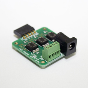
- One BlinkStick Pro v1.0
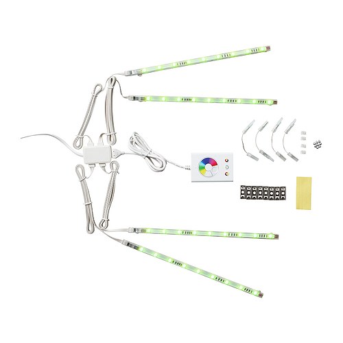
- One Ikea DIODER
- A soldering iron
- Some solder
- Some wire
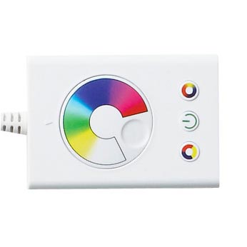
Step 2 - Open the main board case
Pry open the case. Best way to do it is with a screw driver on one of the sides.
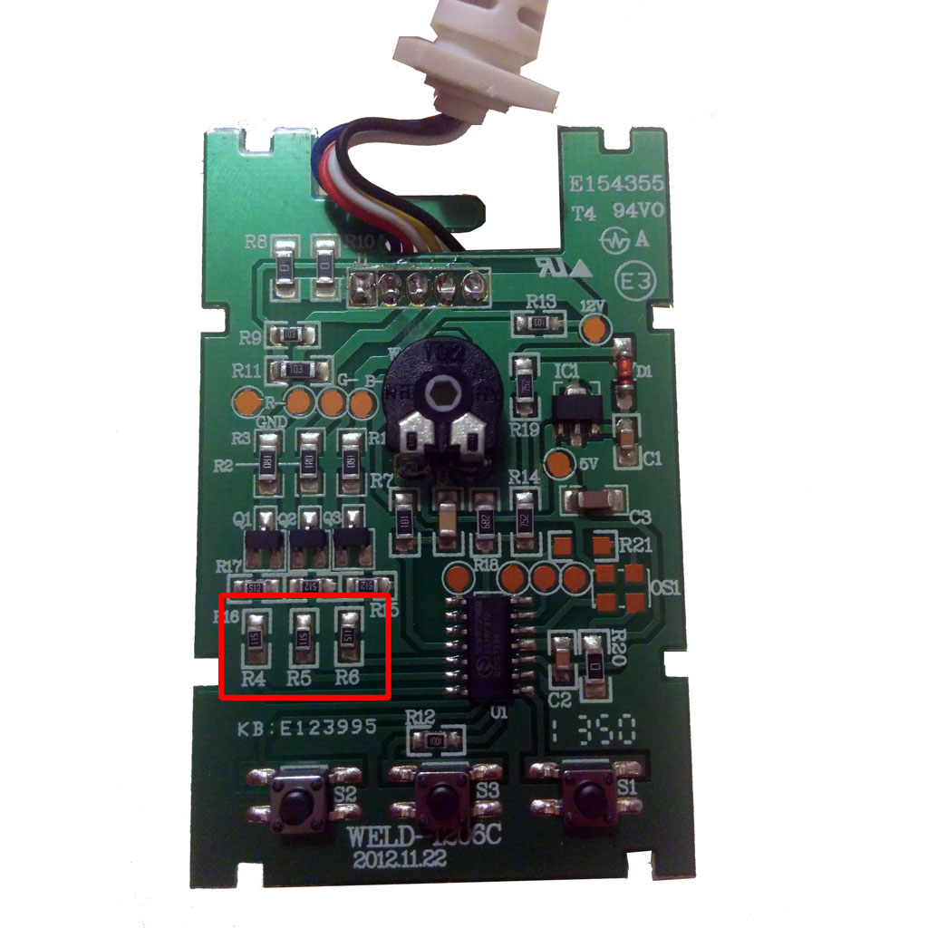
Step 3 - Remove the resistors
Remove SMD resistors R4, R5 and R6.
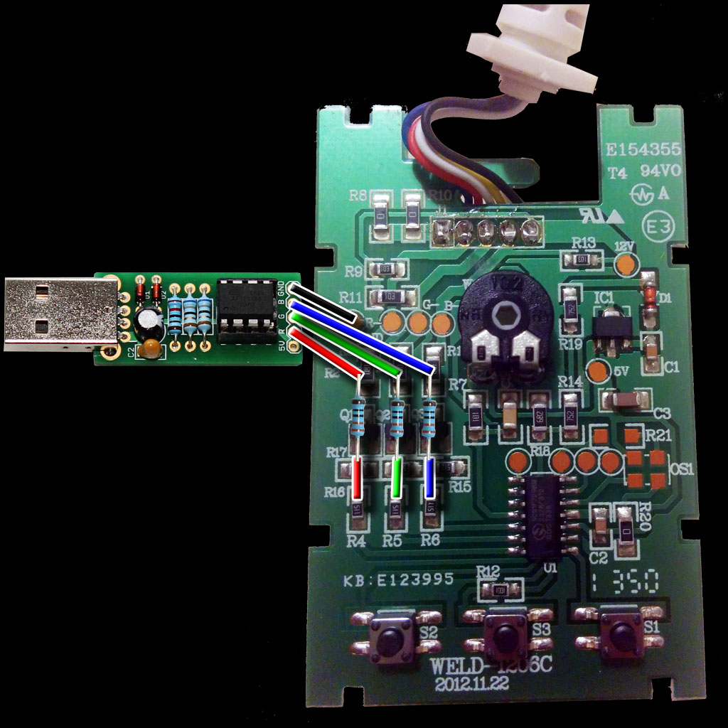
Step 4 - Wiring BlinkStick Pro
Assemble BlinkStick Pro then wire it up to the main DIODER board according to the schematic. Use the supplied 3 x 330 Ohm resistors color coded orange, orange, black, black and brown to connect them to the pads on the board.
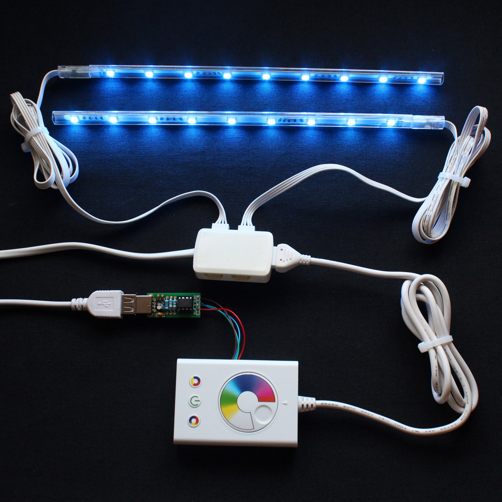
Step 5 - Using BlinkStick Pro with DIODER
Connect BlinkStick Pro to the computer and plug the DIODER to the mains. It still needs the external power supply to drive the LEDs.
Add an Ambilight notification to the client application and link it to the BlinkStick Pro. The client application will calculate the average color on the screen and display it on the LED strips.
Once you finish the hack, the controls on the DIODER will not work any more. If you ever want to go back to all of the original features of DIODER, just remove the wires you have soldered in Step 4 and put the resistors back in.
Inverse mode
In order to use IKEA DIODER with BlinkStick software, you have to use inverse mode.
Client applicationYou can set the inverse mode for your client application:
- Open the main menu BlinkStick -> Manage
- Select your BlinkStick
- Change control parameter to Inverse
- Hit Apply button
This setting will be memorized for the BlinkStick with the serial number.
Python Control ScriptThe control script that comes with Python pip package contains the mode selection option. For example:
blinkstick --set-mode 1
- 0 - standard mode
- 1 - inverse mode
- 2 - WS2812 LED control mode
Mode is stored inside BlinkStick and once set is no longer required to set it unless you want to change it.
Python codeBlinkStick object in Python module exposes set_mode method to enable the inverse mode.
stick = blinkstick.find_first()
stick.set_mode(1)
stick.set_color(name="blue") # this correctly sets color to blue