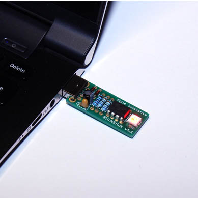
Build your BlinkStick v1.1
Step 1 - Tools
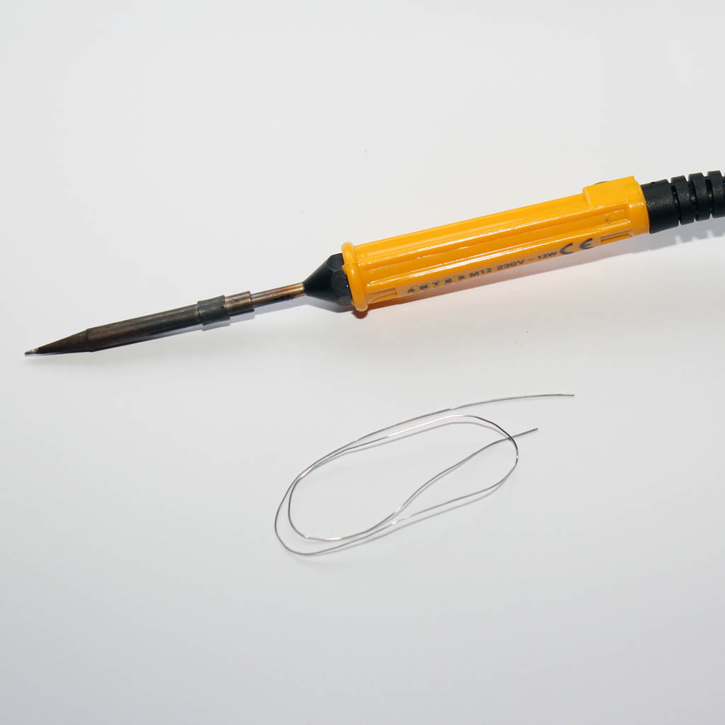
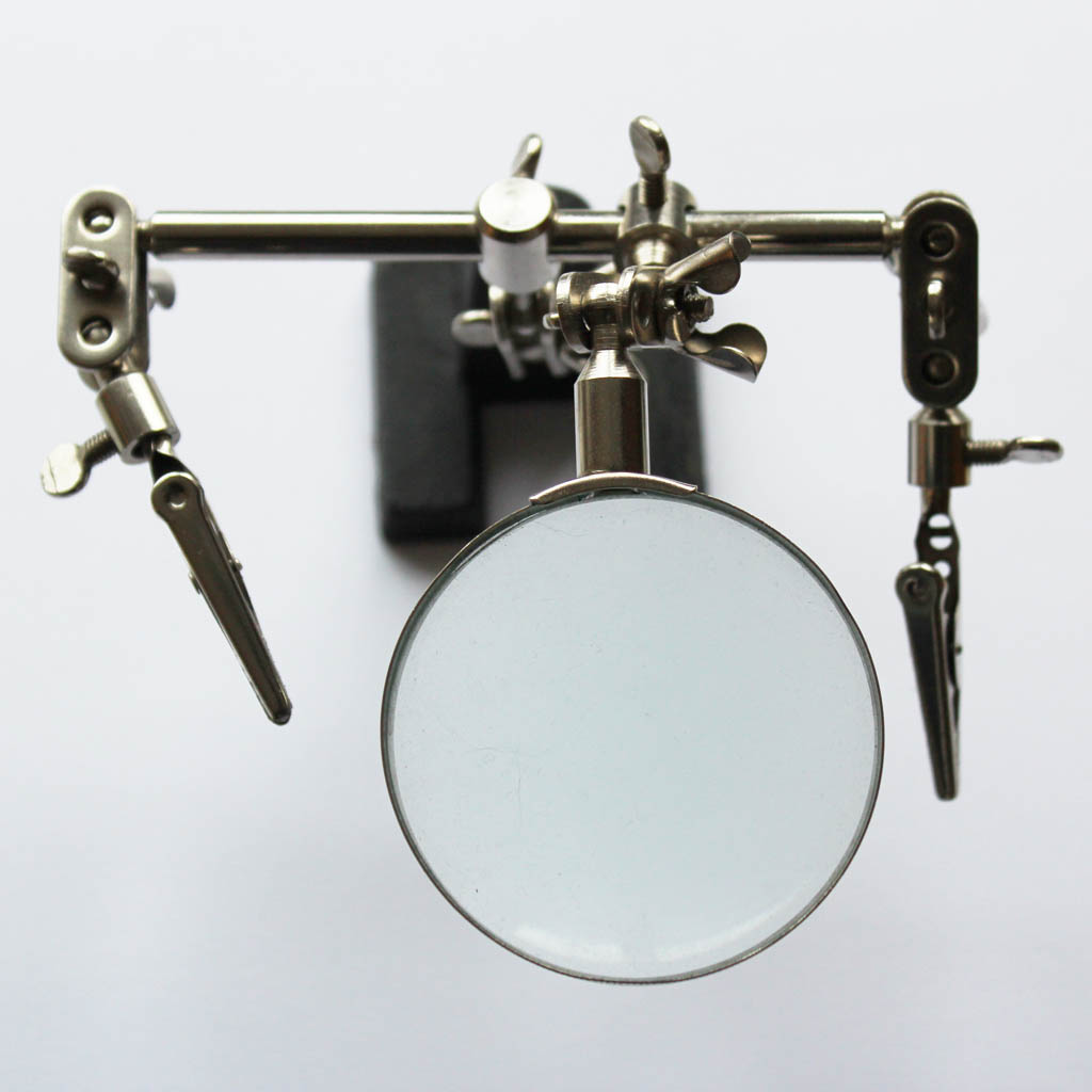
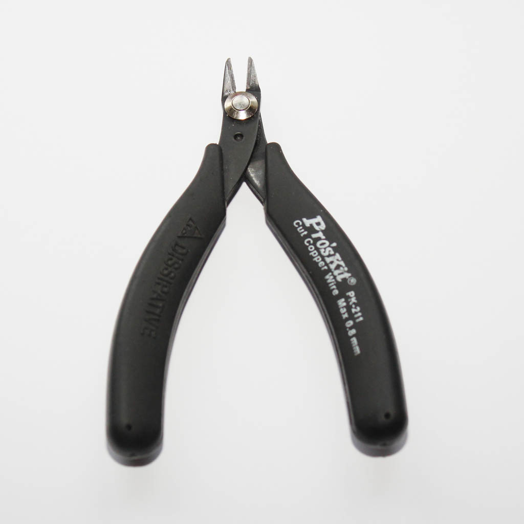
To solder the BlinkStick you will need:
- Basic soldering iron and some solder
- Helping hands (not necessary but very helpful)
- Cutters, to cut excess wires
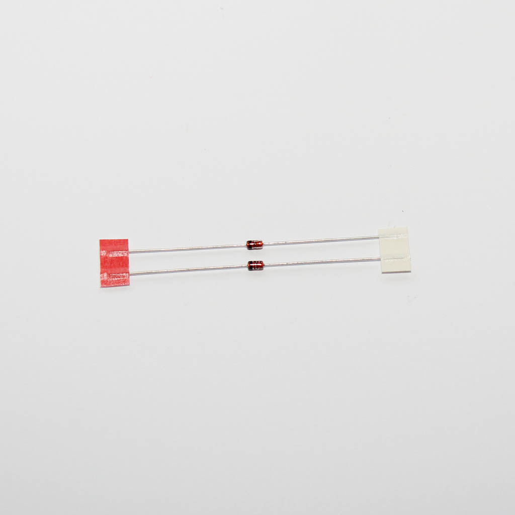
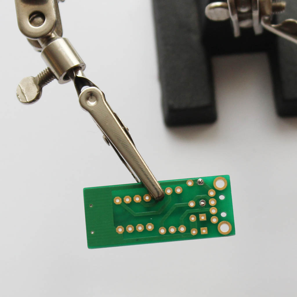
Step 2 - Diodes
Solder zener diodes D1 and D2. Make sure the polarity is correct! The black stripe on the diode is represented by a white stripe on the component's symbol.
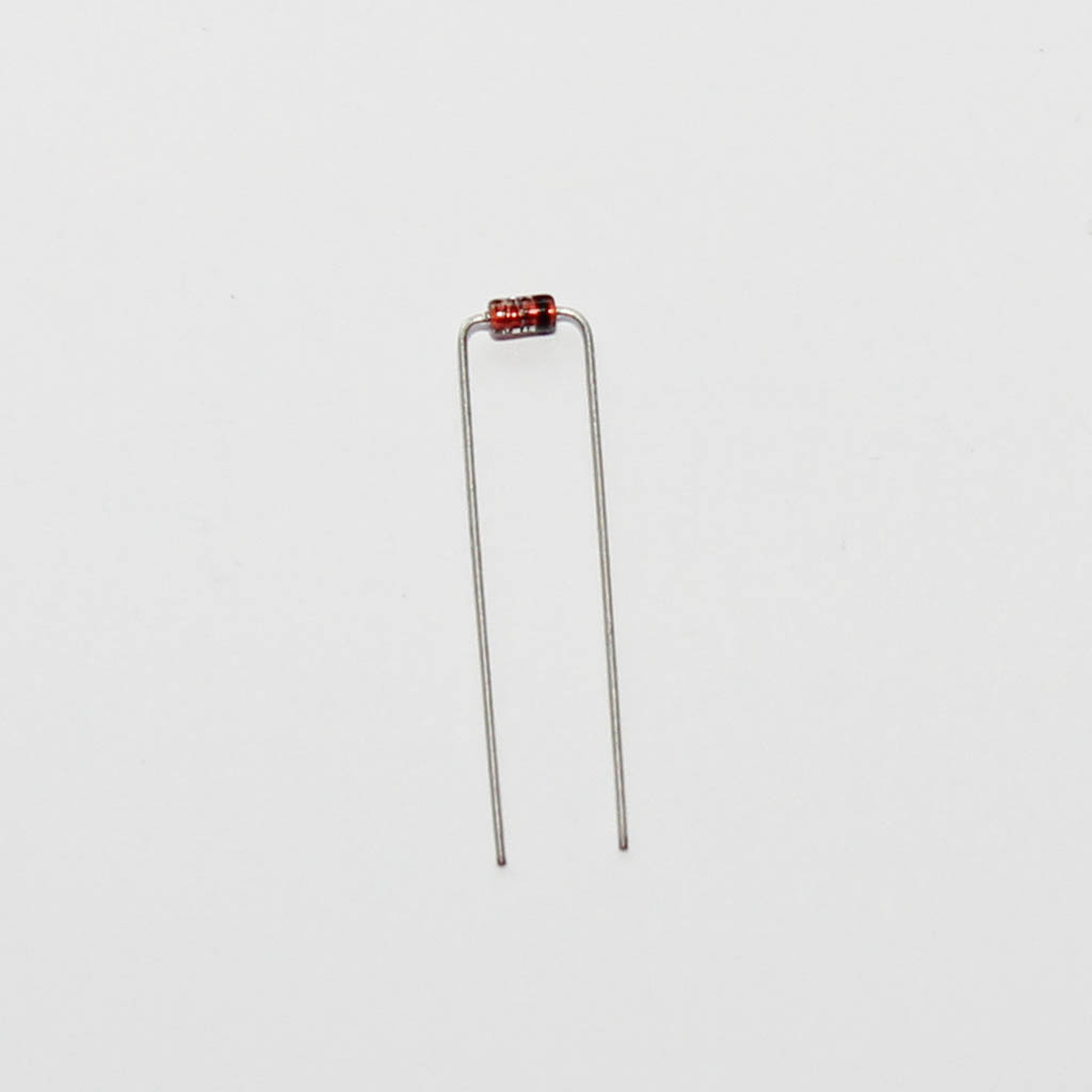
Bend diode pins as close to the diode as possible and then bend the pins outwards once inside the board so that they stay secure in the location when soldering
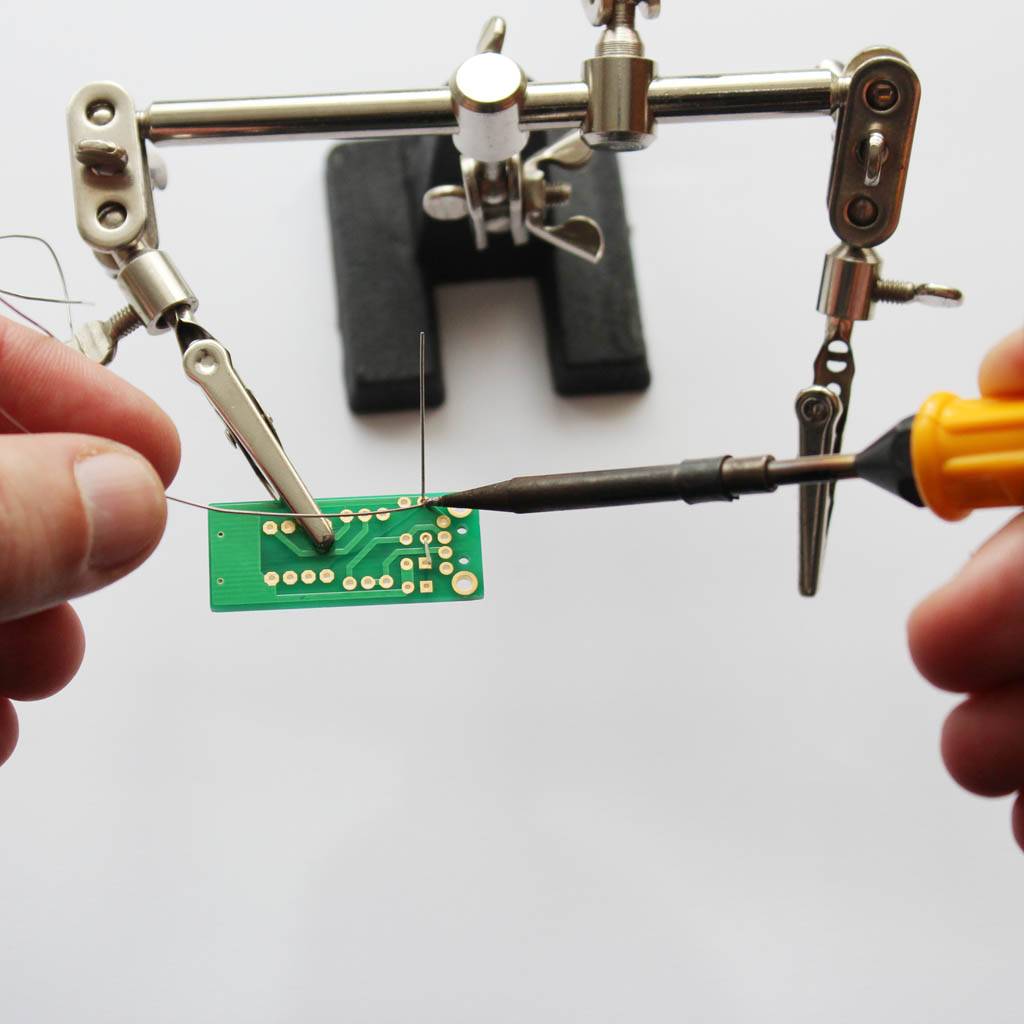
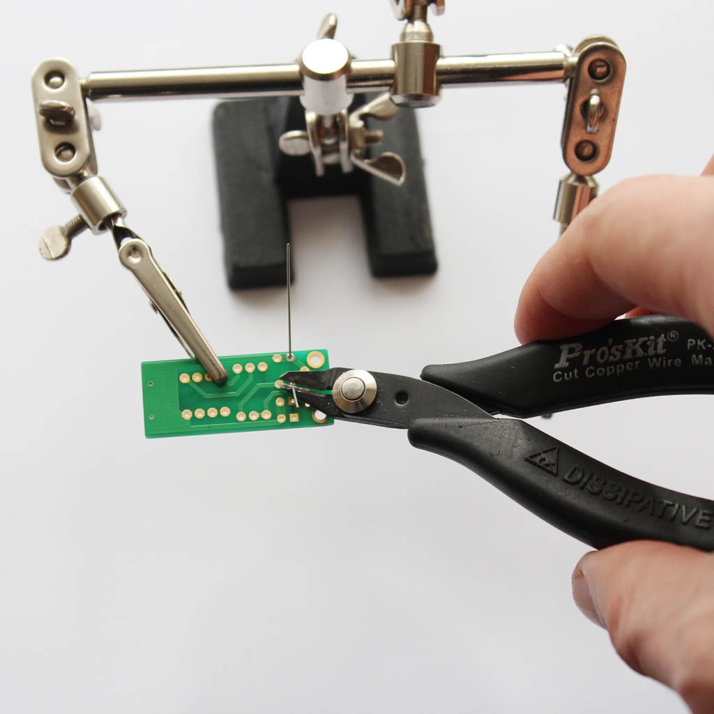
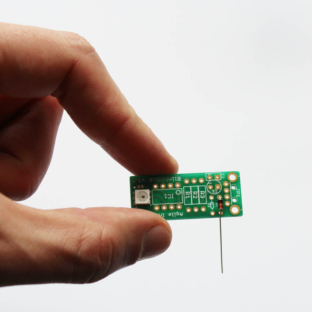
Step 3 - Soldering
Solder the diodes and cut the excess wire near the solder joint.
Use the same technique when soldering the rest of the components.
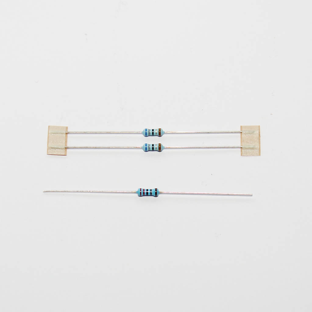
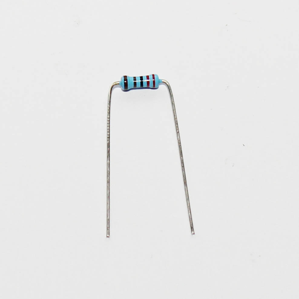
Step 4 - resistors
Solder the resistors. There are 2 types of resistors:
- R1, R2 (68 Ohms) - Blue, gray, black, gold, brown
- R3 (2.2 kOhms) - Red, red, black, brown, brown
Remember to bend resistor pins outward so that they stay in their locations.
Step 5 - Capacitor C1
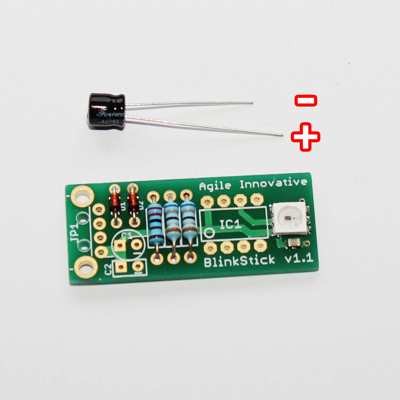
Solder the electrolytic capacitor C1. Capacitors have polarity and the longer pin is positive. The negative pin is displayed on the board with a minus sign next to it.
Step 6 - Capacitor C2
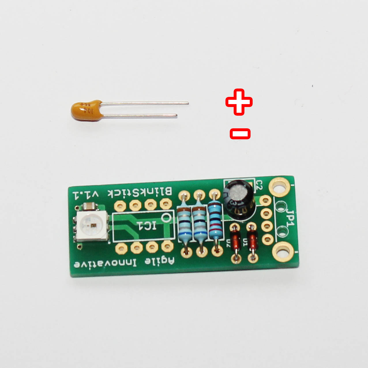
Solder the tantalum capacitor C2. It also has polarity as displayed in the picture with longer pin being positive and shorter - negative.
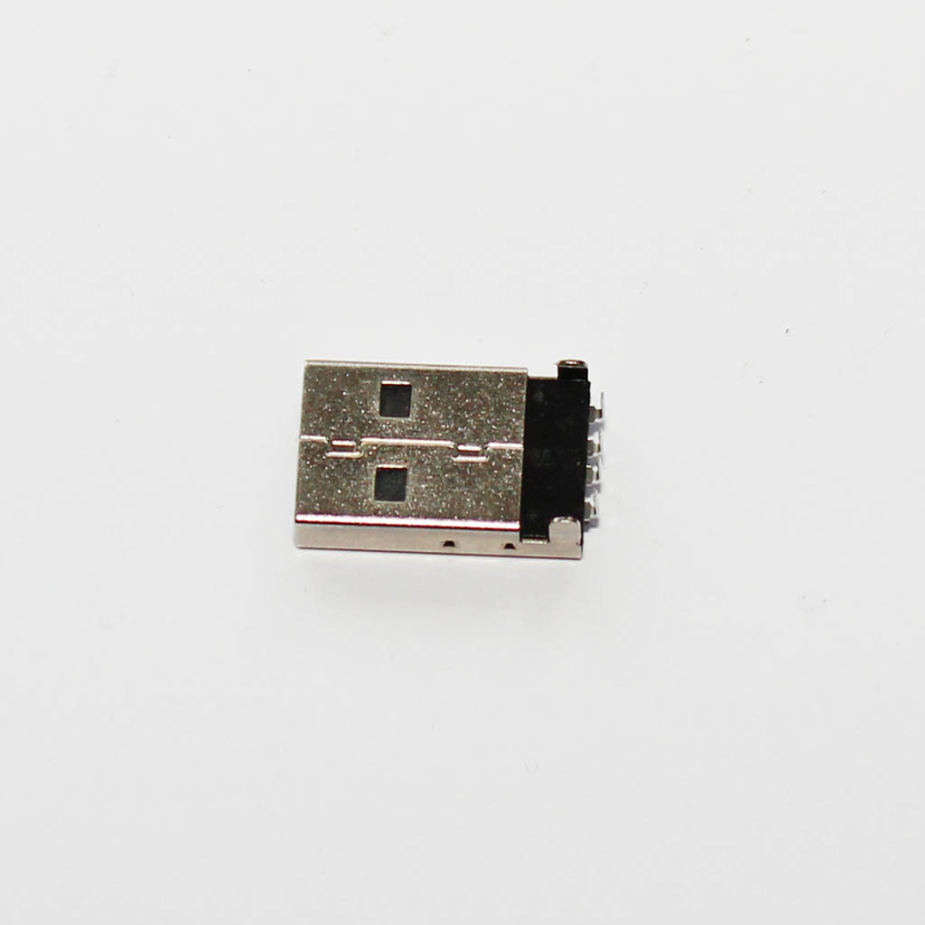
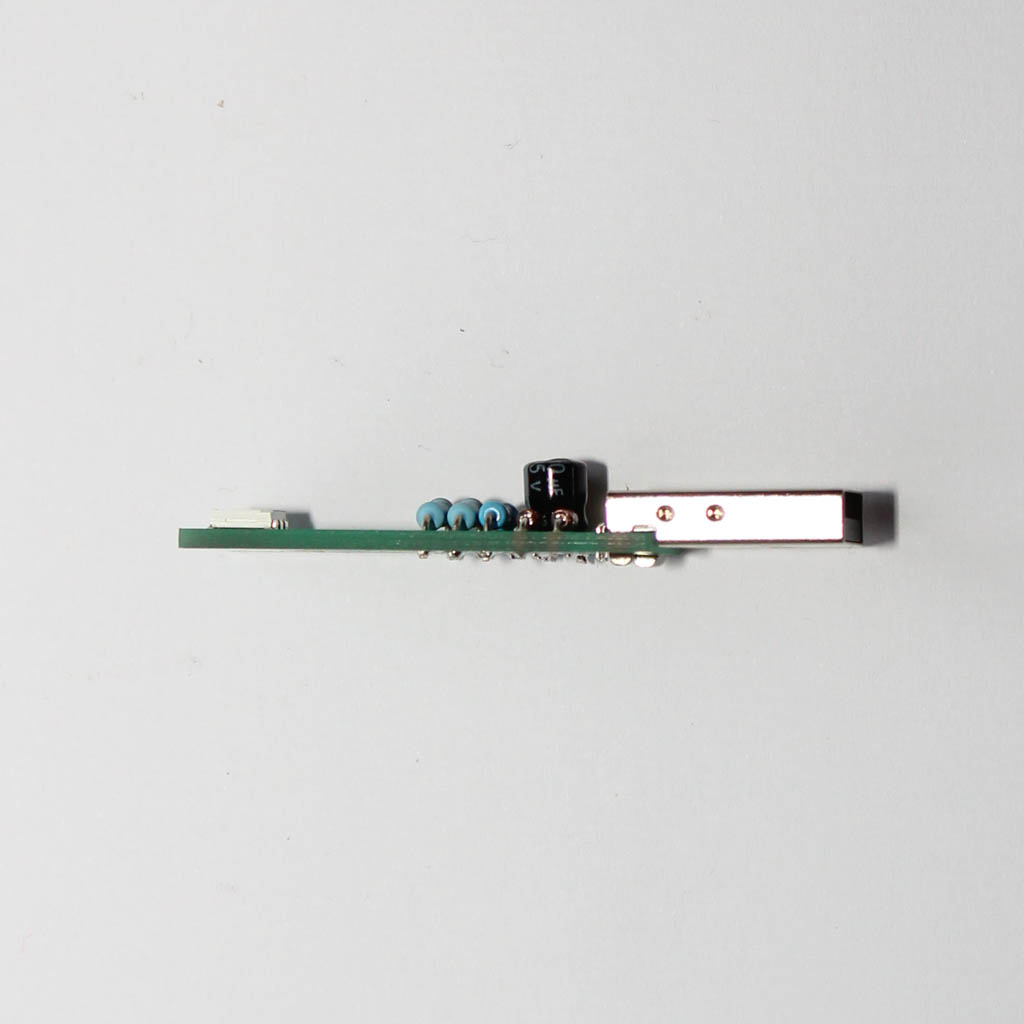
Step 7 - USB plug
Solder USB plug JP1. The board and the plug should be nice and straight.
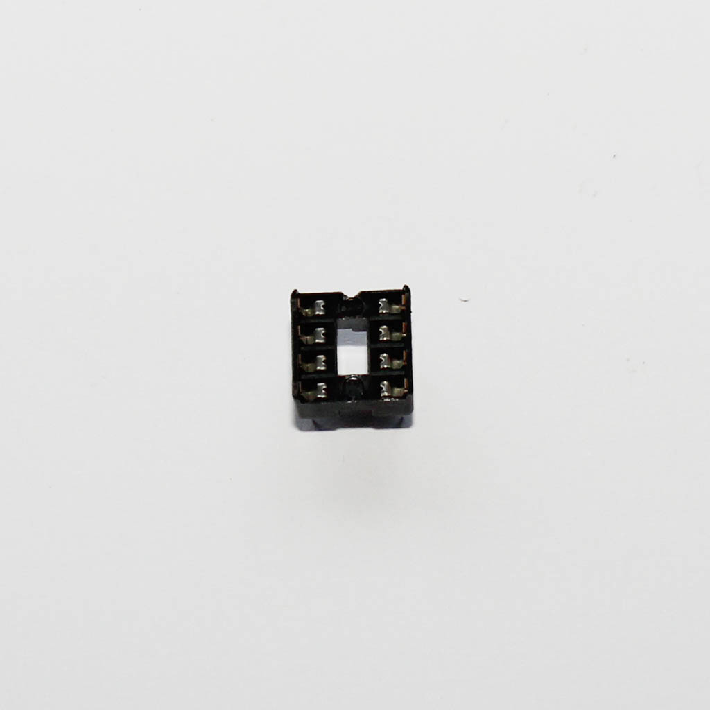
Step 8 - IC socket
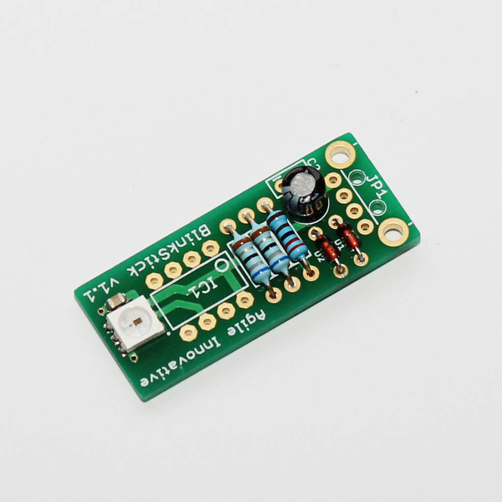
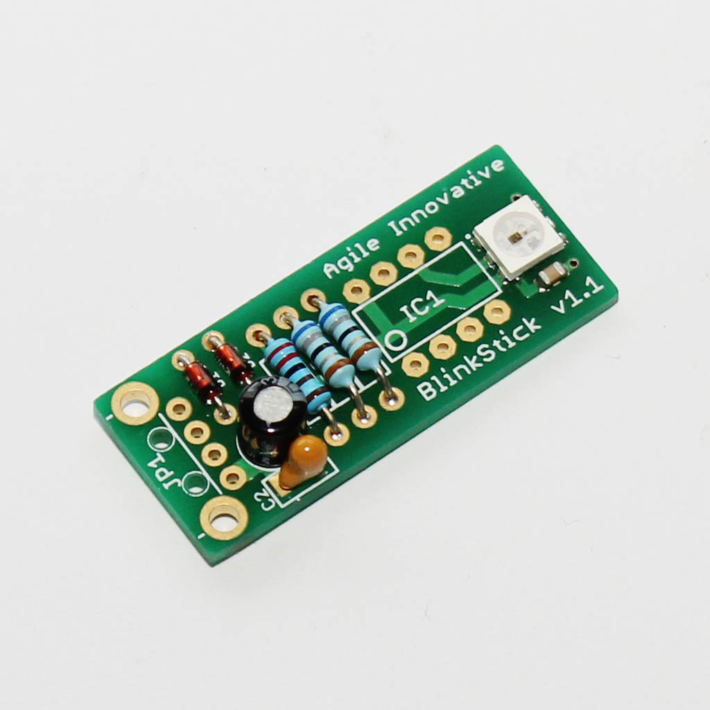
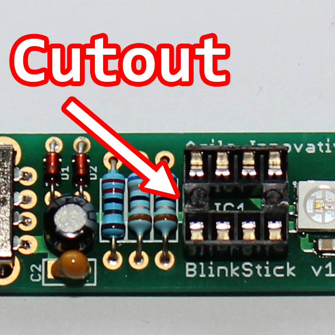
Solder the optional IC1 socket. The ATTiny85 chip will be placed into the socket at a later step. The socket has a cut-out on one edge. It should be aligned as displayed in the second image.
You can also solder the chip directly to the board. In that case just follow the chip alignment instructions in the next step to correctly place it and solder the ATTiny85 instead of the socket.
Please note that if you solder the socket it will raise the ATTiny85 chip and slightly obstruct the LED light.
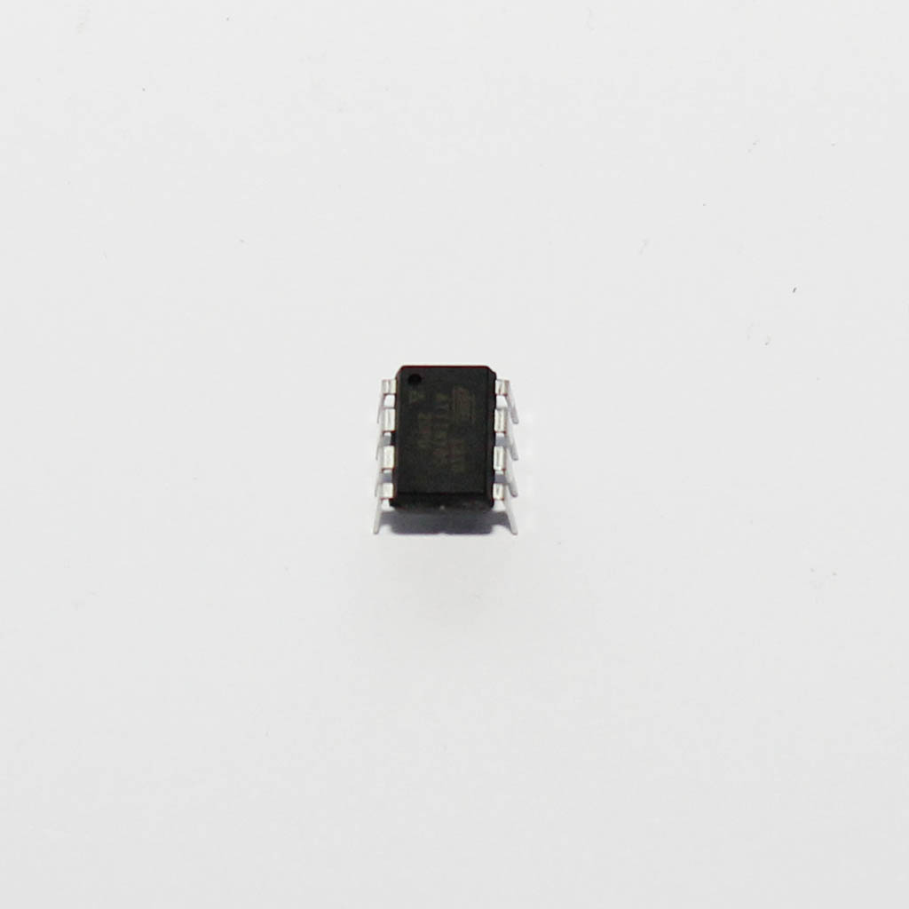
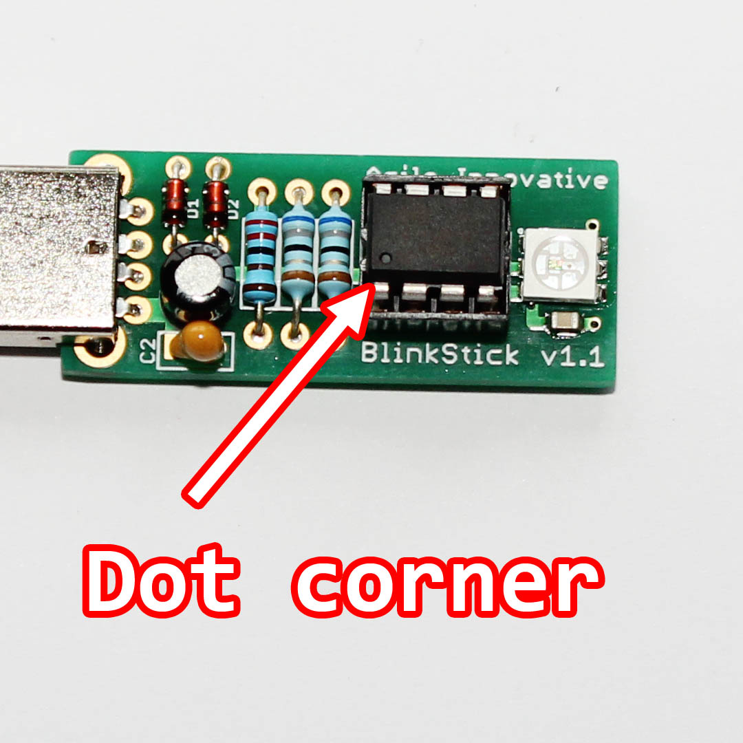
Step 9 - ATTiny85
Plug in the ATTiny85 IC into the socket. Make sure that you plug the chip correctly! The dot on the chip should match the second image.